 Fraunhofer Institute for Applied Optics and Precision Engineering IOF
For ESA‘s scientific earth-observation mission, Sentinel-4, the Fraunhofer IOF is developing the flight hardware of the spectrometer gratings for the NIR-spectral channel including its isostatic mount.
The dielectric reflection grating operates in the spectral band between 750 nm and 775 nm. Such gratings have initially been developed for the manipulation of high-power ultra-short laser pulses. Thanks to a number of advantageous properties, they have now been adapted to space-borne spectrometer gratings for the first time. In particular the required high angular dispersion in combination with an extremely low polarization sensitivity of the diffraction efficiency is not achievable with alternative concepts based on metallic reflection gratings.
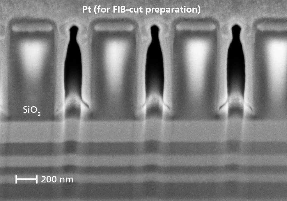
The NIR-grating has a period of 797 nm and is illuminated under 24.5° incidence angle. The grating structure is realized by electron-beam lithography in combination with a reactive ion-etching process in the uppermost SiO2-layer of a custom designed dielectric Ta2O5/SiO2-layer stack (Fig. 2).
An additional novelty is the direct integration of the aperture into the grating surface. The aperture is formed by a so-called black-chromium layer which exhibits a reflectivity well below 5 % over the relevant spectral band. This layer is also structured in a lithographic process ensuring very high position- and size-accuracy. The direct integration of the aperture into the grating surface allows for significant simplification of the mechanical grating mount, as it avoids the need for a separate mechanical diaphragm.
After the lithographic structuring process, the grating substrate is cut to an octagonal contour and isostatically mounted onto a base-plate via Invar-pins and specially developed bipods. The assembly is performed using a three-coordinate measurement tool to ensure the required positioning accuracy of just a few micrometers. Figure 1 shows the assembled qualification model of the grating unit. It was delivered to the project partner Astrium DS in September 2015.
Authors: Uwe. D. Zeitner, Andreas Kamm, Tino Benkenstein, Thomas Flügel-Paul, Gilbert Leibeling